1 button (also used for boot selection) and 1 LED:
| Device | PIN |
|:------ |:---------------- |
| LED0 | 25 |
| SW0 | QSPI_SS_N (*) |
(*) Since the switch is connected to the chip-select pin of the QSPI interface the flash chip RIOT
is running from via XIP, the switch is difficult to read out from software. This is currently not
supported.
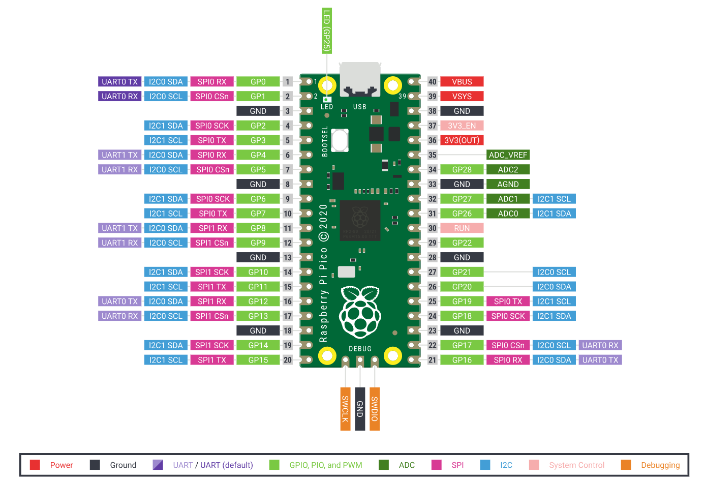
### Pinout

## Flashing the Board
### Flashing the Board Using OpenOCD
Currently (June 2021), only two methods for debugging via OpenOCD are supported:
1. Using a bit-banging low-level adapter, e.g. via the GPIOs of a Raspberry Pi 4B
2. Using a virtual CMSIS-DAP adapter provided by the second CPU core via
https://github.com/majbthrd/pico-debug
Since option 2 requires no additional hardware, this is currently the default. However, you need to
first "flash" the gimme-cache variant of [pico-debug](https://github.com/majbthrd/pico-debug)
into RAM using the UF2 bootloader. For this, plug in the USB cable while holding down the BOOTSEL
button of the Pico and copy the `pico-debug-gimmecache.uf2` from the
[latest pico-debug release](https://github.com/majbthrd/pico-debug/releases) into the virtual FAT
formatted drive the bootloader provides. Once this drive is unmounted again, this will result in
the Raspberry Pi Pico showing up as CMSIS-DAP debugger. Afterwards run: