mirror of
https://github.com/RIOT-OS/RIOT.git
synced 2025-01-16 01:52:44 +01:00
83 lines
3.0 KiB
Plaintext
83 lines
3.0 KiB
Plaintext
/**
|
|
* @defgroup boards_microduino-corerf Microduino CoreRF
|
|
* @ingroup boards
|
|
* @brief Support for the Microduino CoreRF board
|
|
|
|
# Hardware
|
|
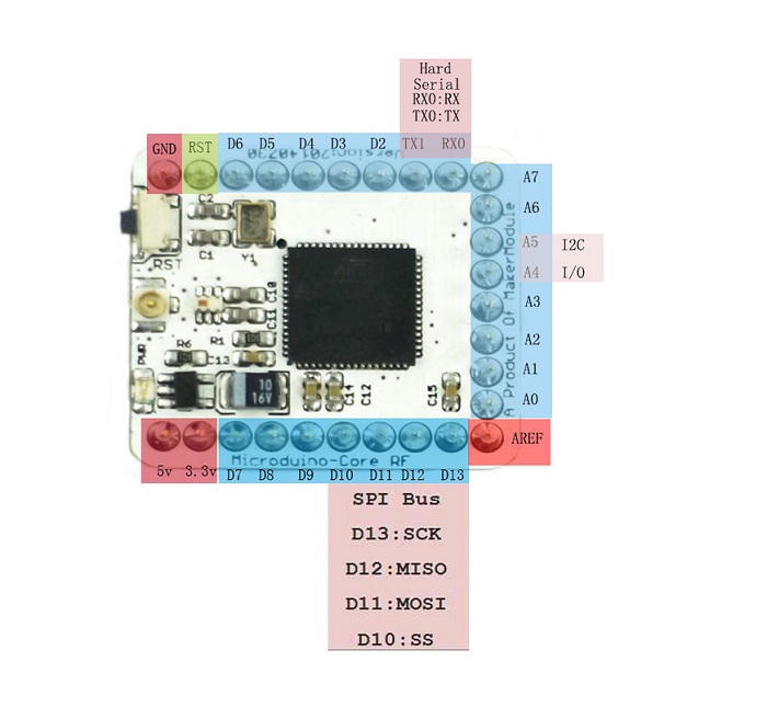
## Pinout
|
|
|
|

|
|
|
|
Warning: Unlike on other ATmega MCUs, the GPIOs are not 5V tolerant.
|
|
|
|
## Board
|
|
The board is just a breakout for the ATmega128RFA1 MCU.
|
|
|
|
## MCU Details
|
|
| MCU | ATmega128RFA1 |
|
|
|:------------- -|:--------------------------|
|
|
| Family | ATmega |
|
|
| Vendor | Atmel |
|
|
| Package | QFN/MLF |
|
|
| SRAM | 16K |
|
|
| Flash | 128K |
|
|
| EEPROM | 4K |
|
|
| Core Frequency | 8MHz (16MHz no power save mode) |
|
|
| Oscillators | 32.768 kHz & 16 MHz |
|
|
| Timerr | 6 ( 2x8bit & 4x16bit ) |
|
|
|Analog Comparator| 1 |
|
|
| ADCs | 1x 15 channel 6 to 12-bit |
|
|
| USARTs | 2 |
|
|
| SPIs | 3 (1 SPI & 2 USART SPI) |
|
|
| I2Cs | 1 (called TWI) |
|
|
| Vcc | 1.8V - 3.6V |
|
|
| Datasheet / Reference Manual | [Datasheet and Reference Manual](http://ww1.microchip.com/downloads/en/DeviceDoc/Atmel-8266-MCU_Wireless-ATmega128RFA1_Datasheet.pdf) |
|
|
| Board Manual | [Wiki Page](https://wiki.microduinoinc.com/Microduino-Module_CoreRF) |
|
|
|
|
The MCU comes with a 2.4 GHz IEEE 802.15.4 radio that is compatible with the
|
|
Atmel AT86RF23x line of transceivers with the only difference being that it is
|
|
not being accessed over an SPI bus, but instead the radio registers are directly
|
|
mapped into memory.
|
|
|
|
# Flashing RIOT
|
|
Flashing RIOT on the CoreRF is done using the SPI method.
|
|
Using a cheap FT232H breakout board, connect the board as follows:
|
|
|
|
| FT232H | Microduino CoreRF |
|
|
|:------ |:----------------- |
|
|
| D0 | D13 (SCK) |
|
|
| D1 | D11 (MOSI) |
|
|
| D2 | D12 (MISO) |
|
|
| D3 | RST (Reset) |
|
|
| 3.3V | 3.3V |
|
|
| GND | GND |
|
|
|
|
Now you can simply type
|
|
|
|
`make flash BOARD=microduino-corerf`
|
|
|
|
This should take care of everything!
|
|
|
|
You will need a separate adapter for UART:
|
|
|
|
| FT232R | Microduino CoreRF |
|
|
|:------ |:----------------- |
|
|
| TX | D0 |
|
|
| RX | D1 |
|
|
|
|
# Troubleshooting
|
|
|
|
## Using the external crystal oscillator (Transceiver Crystal Oscillator) and deep sleep
|
|
|
|
When the external crystal oscillator is used as system clock and the device is put into deep sleep mode it seems that
|
|
the clocks for all peripherals are enabled and set to the smallest divider (highest frequency). This leads to a higher
|
|
power consumption. When the device should be put into deep sleep it is recommended to use the internal RC oscillator
|
|
as system clock source.
|
|
|
|
## Pin Change Interrupts
|
|
|
|
More pins can be used for hardware interrupts using the Pin Change
|
|
Interrupt feature. See @ref boards_common_atmega for details.
|
|
|
|
*/
|